Introduction to Piping Flanges
Drawing pipes and pipe flanges in CAD can be a real headache if you do it the old-school way. You’ll need to draw each part of the pipe system, including the pipe flanges, holes, and fasteners. This method can take a lot of time, especially when working on a complicated design.
The manual process usually goes like this:
- Starting with Basic Shapes: The flange is initiated as a basic circle representing its outer diameter. If drawing the flange in elevation view it will appear rectangular.
- Adding Details: Further elements are drawn to represent the inner diameter and the bolt circle, where the bolt holes are located. Everything must be drawn with accuracy.
- Drawing Bolt Holes: If drawing in plan view, bolt holes are added around the bolt circle at specific intervals. This requires precise measurements to ensure the holes are evenly spaced and accurately sized.
- Adding Flange Thickness: The thickness of the flange can be defined in the elevation view, or if creating the flange in 3D you can start by extruding the 2D circle and then subtract the holes to achieve just the basics
- Checking Standards and Specifications: Depending on the specific type of flange (like weld neck, slip-on, etc.), additional details are added. These details must comply with industry standards and specifications.
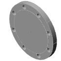
More about drawing a 2D flange
Definition and Purpose of Piping Flanges
A piping flange is a critical fitting used in piping systems, providing a means for assembling and disassembling pipes and other components.
In simple terms, a flange can be described as a mechanical fitting typically used in piping systems to connect various sections of pipe or to connect a pipe to other components like valves, pumps, or vessels.
It’s a flat, circular plate with fastened bolts, allowing two flanges to be joined with a gasket between them to ensure a tight seal.
Flanges are important for creating a modular piping system, as they allow for easy assembly and disassembly for maintenance, repairs, or system modifications.
Typical Flange Types
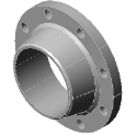
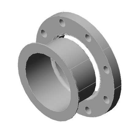
- Weld Neck Flanges: Known for their tapered hub and strength, weld neck flanges are widely used in high-pressure systems.
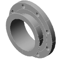
- Slip-On Flanges: These flanges slide over the pipe and are welded in place.
- Threaded Flanges: Ideal for low-pressure, non-critical applications, these flanges are screwed onto pipes.
- Lap Joint Flanges: Used with stub ends, these flanges are great for systems requiring frequent dismantling.
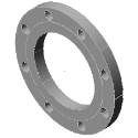
- Blind Flanges: These solid flanges seal the end of a piping system.
Mech-Q simplifies the drawing process in CAD for each flange type with precise specifications and dimensions.
Other flange types avaiable are listed below.
Typical Flange Materials
- Carbon Steel and its Application: Carbon steel flanges offer strength and durability. In CAD, carbon steel can be selected for material properties used in a Mech-Q until specs are re-defined.
- Stainless Steel: Stainless steel flanges resist corrosion and are suitable for various environments. Mech-Q’s material library allows you to select the right grade of stainless steel for your specific applications.
And many more are covered below.
As you lay out a pipe system, you must consider factors like pressure, temperature, and the nature of the transported materials to allow for safety in the piping network. Various flange types (such as the ones listed below) can be selected depending on the application.
Functions of Piping Flanges
Piping flanges provide structural support, ensure leak-proof connections, and allow for a flexible system.
Their mechanical properties and sealing capabilities are crucial for system integrity. Mech-Q’s CAD tools allow engineers and drafters to factor in these requirements during the drawing phase.
Automating the process of drawing Piping Flanges
Flanges can be complicated to draw by hand in CAD – especially if drawing them in 3D.
Drawing tools like Mech-Q can make the drawing process a whole lot simpler. It’s like having a CAD expert beside you to speed up the process. Mech-Q includes ready-to-use pipes and flanges.
You pick what you need, size, and spec, and Mech-Q automatically draws them into your layout. This means less time drawing and measuring and more time getting other things just right.
In the video below we dive deeper into flanges and how Mech-Q can help you draw them.
Piping Flange Design
Mech-Q streamlines the design process, offering templates and customizable options for flange design. This software provides a step-by-step guide to designing flanges, ensuring that all specifications are met efficiently.
Once a project spec and software settings are established, they can be saved for future projects. Multiple project types can be built in Mech-Q to cut back even further on drawing time.
Choosing Flange Specs
Standard dimensions for flanges are critical for ensuring compatibility and functionality. Mech-Q adheres to these standards while providing the flexibility to change dimensions where needed.
This is where Mech-Q proves to be invaluable. It comes pre-loaded with a comprehensive database of standard flange dimensions that align with industry norms. This database covers various flange types and sizes, ensuring that whatever you design will be compatible with real-world piping components.
Whether you’re working with common flange types like weld neck, slip-on, or blind flanges, Mech-Q has the specs you need.
Questions we have covered so far:
What are piping flanges used for?
Piping flanges connect pipes, valves, pumps, and other equipment in a piping system, allowing for easy assembly and maintenance.
How does Mech-Q aid in designing piping flanges?
Mech-Q provides CAD tools that simplify the drawing process, offering many specs to choose from, along with customizable options for fast and efficient pipe and flange drawings.
What are the main types of piping flanges?
The main types include weld neck flanges, slip-on flanges, threaded flanges, lap joint flanges, and blind flanges. Although many other types are available in Mech-Q
Why are material properties important in flange design?
Material properties determines flange performance. A material drop-down is provided in Mech-Q with various types to choose from.
Can Mech-Q design custom flanges?
Yes, Mech-Q can design custom flanges, providing flexibility to meet specific requirements while ensuring compliance with industry standards.
How does CAD improve the flange design process?
Yes, CAD improves accuracy and efficiency and allows for easy modifications and customization in the flange design process.
Are there standard dimensions for piping flanges?
Yes, there are standard dimensions for piping flanges. Mech-Q uses the latest spec to match your requirements.
Step-by-Step Example: Designing Piping Flanges Using Mech-Q
Follow a detailed tutorial exploring the practical application of Mech-Q in designing various types of piping flanges. This section includes a comprehensive guide to accessing and utilizing Mech-Q’s features for efficient and precise flange design.
Tutorial: Using Mech-Q for Piping Flange Design
Getting started with Mech-Q in your CAD program is easy. You can find it at the top of your screen, either in the pull-down menu or the toolbar. For this guide, we’ll use the Ortho Pipe tool, which is where flanges are located.
3-minute video walkthrough on how to create a piping flange.
In the Mech-Q dialog, you can select either single, double line or 3D. In the video example below, we are working with the 3D option. To begin, just double-click on the flange thumbnail,
Next, you’ll have the option to choose the type of flange and other options like showing centerlines.
- Blind Plate
- Flat
- Slip-On
- Welding Neck
- Lap Joint
- Long Neck
- Ring Joint
- Socket Weld
- Boss
- User-defined
The flange routine allows users to choose many different settings including flange thickness, diameter, and fasteners. These consist of:
- Centers 2D (On/Off)
- Draw hidden lines 2D (On/Off)
- Raised face or plane
- Slip On flanges (if applicable)
- Draw as plate flange.
- Gasket (On/Off)
- Bolts or Studs (for BOM only)
Then select the flange type from the ” Type ” list at the lower left – then to begin the drawing process, select the icon corresponding to the flange and view required. See the insert points (marked with an X) to choose which side of the flange you need to draw.
After selecting the Pick Point, the dialog closes and you are prompted to define the insert point and up-flow direction, after which the flange pops into place. To continue, you can add a straight piece of pipe by hitting enter, selecting the endpoint, and pressing enter again.
If you want to add a bend in the pipe, like an elbow, it’s just as straightforward. Hit enter, choose which way the pipe should go, and rotate it to fit your design. We suggest using polar tracking to make your rotations snap at various angles.
To add another type of flange, like a weld neck, just choose where it should go, set the direction, and it’ll insert automatically. Mech-Q can also put in elbows automatically at 90-degree angles. To finish up, just add the last flange and another straight pipe section the same way.
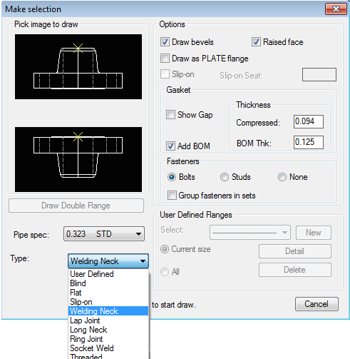
Figure shows a typical dialog menu with various settings available.
How to define your custom Flanges
You can also add a custom flange from the Flange Type List. This will allow you to quickly recall the settings of a flange later. First, select ” User Defined” from the flange “Type ” list.
Then to define a new Flange select the “< Add New >” item in the “User Defined Flanges ” box “Select ” list. This displays the User Flange Data dialogue. Enter the flange data, then use the button “Save Design ” to save the new flange design.
User Defined Flanges are then displayed in the ” Select ” list. The list can show either all user flanges of the Current Size or All user-defined flanges in the database.
Other piping notes :
Mech-Q provides a quick way to draw either 2D or 3D flanges – each of them can be itemized to a bill of materials for further reporting.
Fasteners are automatically listed in the materials list, which saves a ton of time if you need to itemize the parts.
The Bolts/Studs can be also added to the BOM of either the Pipe end or Fitting end mating flange.
In addition, the Mech-Q manual and tutorial are readily available for download and detailed how-to examples.
5 Good Reasons to Use Mech-Q When Drawing Flanges
1. Versatility in Design: 2D and 3D Capabilities
Mech-Q supports 2D and 3D design environments, making it a versatile tool for engineers, drafters, and inspectors. Whether you are working on detailed 2D blueprints or constructing 3D models for better visualization and analysis, Mech-Q seamlessly adapts to your project’s needs.
2. Comprehensive Flange Library
With an extensive library of flange types and sizes, Mech-Q simplifies the selection process. This library not only includes standard flange types like weld neck, slip-on, and blind flanges but also accommodates other industry standards, ensuring compatibility and compliance in your designs.
3. Customization and Precision
Mech-Q allows for high levels of customization and precision in flange design. You can specify exact dimensions, materials, and even threading details, ensuring that the flanges meet the unique requirements of each project.
4. Integration with Existing CAD Platforms
One of the most significant advantages of Mech-Q is its ability to integrate with popular CAD platforms. This integration enables engineers to keep their existing workflows and share drawings without using a whole other array of CAD software tools.
5. Automated Bill of Materials (BOM) and Fasteners
Mech-Q automates the generation of a Bill of Materials (BOM), which is essential for planning and acquiring materials for a project.. The software also includes options for fasteners, which are automatically listed in the BOM. This ensures that all components, including the flanges and associated hardware, are accounted for so that you don’t have to tabulate them manually.
[custom_button text=”Download a free trial” title=” Download a free trial” url=”https://cadavenue.com/#trial” size=”large” bg_color=”#71BA43″ text_color=”#FFFFFF” align=”left” target=”_self”]