Mech-Q Piping is an add-on for AutoCAD. It is also available within our CAD standalone called AViCAD. It’s a comprehensive Piping drawing module for drawing simple and complex piping systems. Choose from a wide assortment of 2D. Iso and 3D pipe, fittings, flanges and valves + BOM.
[test3]
See also Part 1
We are celebrating a new Mech-Q release - now fully compatible with the latest AutoCAD 2026 and LT 2024/25/26 versions
If you’re in the Piping industry, and you need an affordable and easy way to speed things up – then Mech-Q is an excellent choice.
Why?
Here’s what makes Mech-Q the clear winner when comparing it to other over-priced, clunky and hard to learn piping software.
5 Reasons To Choose Mech-Q Piping:
1. Simplicity – Mech-Q offers a near Zero learning curve. Mech-Q provides the most easiest transition into automated Mechanical drafting. Really, try it and see for yourself just how easy it is.
2. Affordability – Mech-Q is easy on your wallet. Why spend thousands more on software when you can get the same job done with Mech-Q? It’s really got everything you’ll need, built right into the software.
3. Quality – Mech-Q makes you look great. You’ll produce professional looking drawings with little or no effort. And your clients will never know it…
4. Accessibility – Mech-Q is filled to the brim with power. You’ll find hundreds of exclusive tools and functions throughout the Suite. It’s not just a Engineering Tool. We’ve also included drafting routines, beam calculators and many more utilities all organized and ready to use.
5. Flexibility – Mech-Q is fun to use. It has a intuitive dialog interface – which means you won’t have to hunt for symbols and blocks anymore. You’ll be able to get the job done faster and easier too.
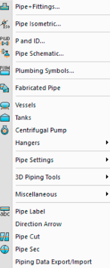
Click to see what's inside the Piping Software
Orthogonal Pipe, Fittings & Valves
A versatile and powerful pipe and pipe fittings utility: 2-D (Single & Double Line). and 3-D (Solids). Compatible with ALL versions of AutoCAD & IntelliCAD
Main Features:
- 2D (Single line & Double) & 3D
- Comprehensive range of pipe &fittings
- Auto-BOM – fully customizable
- BOM Descriptions can be easily edited
- Database editor included.
- Several draw options
- Insulation, customizable layers….
- Easy to use.
- Types of Pipe & fittings included:
- Butt Welded
- Socket Welded
- Screwed
- Victaulic
- Cast Iron (Flanged)
- Ductile Iron (Flanged)
- Ductile Iron (Grooved)
- DI – Mechanical Joint
- Stainless Steel Tube
- Soil Piping (No-Hub)
- PVC
- PVC-DWV
- PE
- Copper
- and more…
Sizes
Pipe size range from DN 15 – 900(1/2″-36″ NB + 1/16 – 3/4″ Tube) -DIN, ISO & ANSIWelded Fittings: DN 15 – 900 (1/2″-36″ NB)SW & Screwed Fittings: DN 6 – 100 (1/4″-4″ NB)Victaulic: DN 15 – 600 (1/2″-24″ NB)Cast Iron (Flg): DN 25 – 450 (1″-18″ NB)Ductile Iron (Flg): DN 80 – 1600 (3″-64″ NB)Stainless Steel (OD)Tube: DN 6 – 100 (1/4″-4″ NB)Tubing: DN 8-16 (1/4-16″ NB)PVC-U & PVC-DWV: DN 15 – 300 (1/2″-12″ NB)Copper: DN 15 – 100 (1/2″-4″ NB)PE-BW: DN 15 – 1000 (1/2″-40″ NB)
Flanges:
- Blind
- Plate
- Bossed
- Welding neck
- Slip-on
- Lap Joint
- Ring Joint (RTJ)
- Long Neck
- Socket weld
- and User Defined flanges
Table A – Table J (Australian)DIN PN10-PN100ANSI: 150-2500
Valves:
- Ball valves
- Gate valves
- Glove valves
- Check valves
- Angle valves
- Plug valves
- 3-Way
- 4-Way
- Butterfly valves and
- Control valves
- and User Defined valves
Isometric Piping
The Pipe Isometric Utility will generate pipe isometric diagrams and pipe spools drawings.
Main Features:
- Comprehensive range of pipe &fittings
- Auto-BOM – fully customizable
- BOM Descriptions can be easily edited
- Database editor included
- Sizes of symbols can be changed by user
- Several scaling options.
- Custom symbols can be added.
- Iso-Dimensioning tools included
- Insulation, customisable layers….
- Easy to use.
Iso Piping BOM customization options include:
- Some BOM Fields can be turned On/Off
- Custom BOM descriptions of pipe/fittings
- BOM Balloons options
- Several leader styles
- BOM Stock Codes option
- Custom BOM remarks
- Custom BOM ratings notes
- Custom BOM field length, width and insertion
- Custom layers, text font, text size…
- Custom fields headers….
Other module include…
Pipe Schematic/Single Line Pipe Diagram
This is a Single line pipe generator. The routine will allow the user to effortlessly draw simple or complex pipe schematics. The user is simply asked to pick points to generate the pipe and at each point the user can pick from a comprehensive icon menu to select the appropriate fitting, valve, pump gauge or hanger. The user is also given the option to draw a LEGEND of the used symbols and/or to form a Bill Of Materials of the fittings and pipes used to draw the schematic or single line pipe diagram.
Vessels Module
Main Features:
- Easy change of design parameters
- 2D and 3D option
- Horizontal & vertical vessels
- Several nozzels can be added to vessel body & heads
- (Nozzel size, flange type and location – fully customizable)
Heads type include:
- Ellipsoidal
- Hemispherical
- ASME Flanged & Dished
- Flat
- Drawing mode: Complete, Heads or vessel body
- Front, end & plan view draw elevations
- Comprehensive range of sizes.
Centrifugal Pumps Module
Main Features:
- Easy to change and add new designs
- Design parameters fully customizable
- Save pump designs for later use
- Front, end & plan view draw elevations
- Add the designed pump to your drawing with ease.
Pipe Hangers and Clamps Module
- Pipe clips and Riser clamps
- Saddle Clamps and Guides
- U-Bolt Clamps and Guides
- Pipe Shoes
Main Features:
- Large selection of sizes & designs
- Option to add fasteners
- Display of design safe loads
- Front, end & plan view draw elevations
Pipe & Instrumentation Diagram (P&ID)
The module covers all the required symbology to generate drawings with intelligent data. This application covers the standard Piping and Instrumentation symbology outlined in the ANSI/ISA-S5.1-1986 code. However you can also add new symbols of your choice and the utility gives you full control of all the symbols sizes, layers, fonts and the data associated with the valves, equipment and instruments used. The program also lets you add your own symbols with ease.
The P&ID components have been split in categories for easy selection:
- Pipe & Fittings
- Equipment
- Valves
- Instrument Equipment
- Instrument Balloons Symbols & Tags
- Functions Blocks
- Miscellaneous
You can change application settings using the P&ID Configuration (CFG) – Settings. For example, you can have the program change from Flanged valves to Socket Welded valves at a predetermined “small” size.
Some of the Main Features are:
- Easy to use
- Large range of symbols included and others can be added with ease.
- Fully customizable: Sizes, layers, symbols
- Auto-BOM
- Auto-labeling line specs & valves tags
- Many More
For larger office a Mech-Q Network Module is also available.
Download this Piping Software Module!
Trial is available.
Download Mech-Q Trial
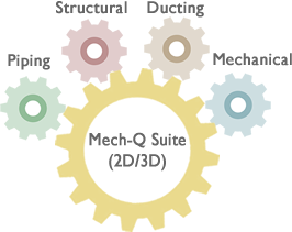
Still want to explore some more? The image below is interactive. Click on each module “gear” to find out more about the other modules.