Pipe Spool Drawings in CAD
Overview
Creating pipe spool drawings using CAD engineering software is crucial for efficient fabrication and detailed shop drawings. Integrating advanced data extraction tools, like those found in AViCAD, AutoCAD, and Mech-Q, can significantly improve efficiency, quality assurance, and cost-effectiveness.
This guide combines the importance of pipe spooling and efficient fabrication with a detailed workflow for exporting the Bill of Materials (BOM) using advanced CAD tools like our 2D/3D Piping module.
What is a Piping Spool?
A pipe spool is a prefabricated piping section used in pipe fabrication. It is typically assembled off-site and transported to the construction site for installation. A pipe spool consists of interconnecting pipes, fittings, and valves that are typically pre-welded and pre-tested before delivery.
Pipe spools are designed based on the Bill of Materials (BOM), which includes a detailed list of all the materials, components, and specifications required for the fabrication drawing.
The Role of CAD Engineering Software
3D Modeling and Drawing Creation
- 3D Modeling: Creating a 3D model of the entire piping system allows engineers to visualize the system comprehensively, ensuring that all components fit together seamlessly. This visualization helps identify potential issues before fabrication begins, reducing the risk of errors and rework.
- Drawing Creation: Once the 3D model is complete, it is converted into detailed shop drawings. These drawings provide the necessary specifications and dimensions for each component, guiding the fabrication process and ensuring all parts are manufactured to the correct specifications.
- Role of the Piping Spool: When a piping drawing is broken down into piping spools, the entire piping system is divided into smaller sections or spools based on size and material. Each spool is then fabricated and assembled separately, streamlining the process.
Why Use Piping Spools?
- Prefabricated Parts: Pipe spooling involves prefabricating parts for piping systems. By creating these parts in an offsite environment, the precision and quality of the components are significantly improved. This method decreases the necessity for on-site alterations and speeds up the assembly process.
- Offsite Fabrication: Fabricating pipe spools offsite in optimal conditions ensures higher precision and consistency. It allows for better quality control and reduces the impact of adverse weather conditions or site constraints on the fabrication process.
Workflow for Pipe Spooling
Drawing Segmentation
Breaking down complex drawings into smaller, manageable parts simplifies fabrication. Each segment can be fabricated separately and assembled onsite, improving efficiency and reducing the risk of errors.
Determining Fabrication Order
Establishing the order in which parts are fabricated helps to avoid delays and ensures a smooth workflow. This way, potential bottlenecks can be identified and resolved, resulting in a more efficient fabricating process. Work can also be delegated to separate teams and departments to further streamline and maximize efficiency.
Using Mech-Q for Piping Spools
Inputting a Pipe Spool Drawing
We recommend using direct distance input in 3D to create a single-line pipe route. The steps are demonstrated in the video above.
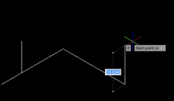
- Specify the Starting Point: Click anywhere in the drawing area (model space).
- Enable Ortho Mode: Press the F8 key to activate Ortho mode, which restricts line drawing to the X, Y, or Z axis.
- Draw the Pipe Route: Move the cursor in the desired direction, specify the length and direction, and repeat to create additional lines. This method lets you quickly sketch your piping spool drawing for further detailing.
Tip: This direct distance input method lets you get a quick sketch of your piping spool drawing so we can snap over this when adding our reducers, flanges, and other pipe fittings.
Inserting Pipe and Fittings
Trace over sketch using Mech-Q, input tees, reducers, and flanges through its dialog interface.

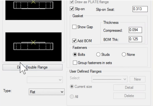
- Select Input Mode: Mech-Q offers single-line, double-line, and 3D input modes, all using the same pipe dialog and settings.
- Specify Components: Define the size, location, fitting type, and material of reducers and flanges.
- Rotate Fittings: Ensure fittings are correctly oriented using Ortho mode during insertion.
Mech-Q has three different input modes: single line, double line, and 3D. Each uses the same pipe dialog and settings. The only difference in our piping spool drawing input is that we work in an isometric view.
Mech-Q enables us to specify the size and location of the reducers and flanges. This also includes selecting the fitting type and material of our components. The dialog interface simplifies the input process as we build our 3D model and draw our piping isometric.
By following these steps, you can effectively utilize the 3D dimensioning tool within Mech-Q to accurately annotate and measure your 3D models.
With certain fittings, Mech-Q will ask us the pipe’s up-flow direction and may also ask us to rotate fittings about our insert point.
Just as we did in our initial piping sketch, we ensure that the various fittings are inset with our Ortho mode active as we rotate them in.
Alternatively, if you do this by hand, you could implement a piping block library and insert fittings individually.
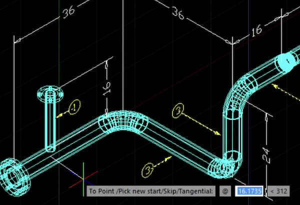
How to Dimension the 3D Drawing
Once our pipe spool drawing is complete, we can use the 3D dimensioning tool within Mech-Q. T

Place Dimension Points: Use a simple 2-point selection to place dimensions on any 3D object without UCS manipulation.
The dimension tool allows for simple 2-point selection, making placing dimensions on any 3D object easy. It does not require any UCS manipulation; the routine handles this transparently.
To use the 3D dimensioning tool, place the two points of the dimension line and confirm whether the axis is the same as the two points entered (co-linear). If the points entered are offset, you can redefine the axis.
Adjust Dimensions: Use commands like “R” to redefine angles or “M” and “F” to mirror or flip the dimension text.
If you’re not satisfied with where the dimension location or orientation, type the letter “R” and choose the desired angle. If the dimension line appears mirrored or upside down, the letters “M” and “F” can mirror or flip the dimension text orientation on the fly.
If you want to insert dimensions in 3D without Mech-Q, you must familiarize yourself with UCS. First, define the new origin using 3 Point UCS and insert your dimension. You may need to rotate, move, or adjust the dimension afterward.
Creating a BOM (Bill of Materials)
Lastly, we will bubble our pipe spool using Mech-Q BOM and insert a schedule. To do so, we activate the Mech-Q BOM tool within the Piping dialog. Note that this tool is specifically designed for piping.
Mech-Q will prompt use for the leader locations for the straight pipe and fittings to add bubbles. You can do so at the command line if you want Skip bubbling a fitting.

- Add Bubbles: Specify leader locations for straight pipes and fittings.
- Generate Schedule: Place the BOM schedule in the desired location within the drawing.
- Update as Needed: Rerun the BOM tool to update the schedule, keeping bubbles or re-labeling as necessary.
If you are not using Mech-Q, we suggest exploring the Express Tools in AutoCAD—you will find a MARKER utility there. This will create a bubble and auto-number it sequentially as you insert the next.
Simplifying BOM Export with AViCAD and AutoCAD
Once all the bubbling is complete, it is time to generate the BOM schedule. Place the schedule in the desired location within our piping spool drawing.
As you change your drawing, you can easily update the BOM and schedule with Mech-Q BOM. Just rerun the BOM, erase the schedule when prompted, and choose whether to keep the bubbles or re-label them.
A BOM is essential for ordering and fabricating parts for a piping spool. It offers a detailed list of all necessary materials, components, and assemblies, assisting in cost estimation, budgeting, fabrication planning, quality control, and assembly.
Advantages of Using AViCAD and AutoCAD
- Speed: Built-in Data Extraction tools automate the BOM process.
- Simplicity: These tools simplify the process of creating a bill of materials, making it easier to manage.
- Flexibility: Easily export data to meet project requirements.
Extracting BOM from your drawing (without using Mech-Q)
If not using Mech-Q, we suggest exploring DATAEXTRACTION command in AutoCAD. Keep in mind that piping block attributes are required in order for a table to be created. Here are the steps to take when using this tool.
- Invoke the Data Extraction Tool: Access the tool in AViCAD or AutoCAD and create a template for future use.
- Set Up Extraction: Select relevant attributes and filter objects to focus on necessary piping components.
- Configure the Table: Adjust columns and handle orphaned blocks to ensure an accurate BOM.
- Combine Identical Rows: Streamline the table for readability and insert it into the drawing.
Advanced Table Manipulation (without using Mech-Q)
- Delete Rows and Columns: Customize the table to meet specific needs.
- Edit Table Content: Modify cell content directly within the table.
- Formatting: Use the Table Style tool for customization.
- Link to Excel: Export to Excel for further editing and integration.
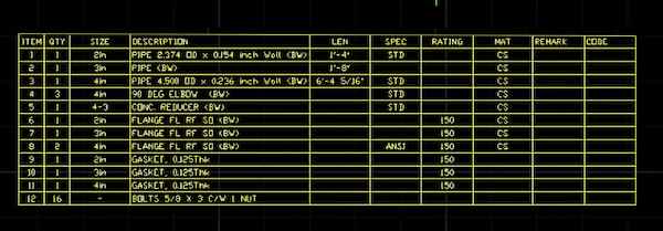
Example of a BOM for a Piping Spool
Below is an example of a Bill of Materials (BOM) for a Piping Spool, which lists the necessary components along with their details.
| Item No |
Description |
Material |
Size |
Quantity |
Remarks |
| 1 |
Pipe |
Carbon Steel |
6″ |
10 ft |
ASTM A106 Grade B |
| 2 |
Elbow 90° |
Stainless Steel |
6″ |
4 |
ASTM A403 WP304 |
| 3 |
Flange |
Carbon Steel |
6″ |
2 |
ANSI B16.5, Class 150 |
| 4 |
Gasket |
PTFE |
6″ |
2 |
Spiral Wound |
| 5 |
Bolt and Nut Set |
Carbon Steel |
3/4″ |
16 sets |
ASTM A193 Grade B7 |
| 6 |
Valve |
Brass |
6″ |
1 |
Gate Valve, ANSI 150 |
A BOM like the one above would ensure that all the necessary components are ordered, tracked, and utilized correctly in the piping spool fabrication.
Wrapping it up
Implementing the tools inside of AViCAD or AutoCAD and using Mech-Q software will create a powerful workflow for pipe spooling and BOM export.
If you choose not to use productivity tools like Mech-Q, we hope that some of the ideas above have simplified and clarified the input process of creating a Piping Spool.