How to start your piping project.
If you are in the oil and gas, chemical, or manufacturing industries, you probably are looking for a straightforward way to draw piping in CAD.
This step-by-step tutorial will look at a typical piping project and what will be required before you start your drawing. We will also cover what you will need to do during the project, and then, finally, we will discuss how to print and distribute your pipe drawing.
Tools you’ll need to create pipe drawings:
When drawing piping diagrams, having the right tools is essential. Here are the key tools you’ll need to start your project:
1. CAD software with Piping Tools preinstalled. Our example video below uses AViCAD, which is AutoCAD-Like and includes various piping modules.
2. Library of piping symbols: Access to a comprehensive library of piping symbols is crucial and includes various fitting types and connections. The Mech-Q tools inside AViCAD will allow us to create these fittings on the fly.
3. Annotations and dimensions: You’ll need a way to easily measure, dimension, and annotate your drawing. Since these tools are included in AViCAD, we need to implement them after the initial input.
Investing in a solid CAD program for engineers equipped with the tools you need will allow you to draw piping in CAD with ease. This way you can create professional-looking piping diagrams and draw them with accuracy using the standards provided in the piping library.
In this tutorial, we discuss how to use Mech-Q to simplify and speed up the input. Try it today for 30 days.
Types of pipes available
Several types of pipes are used in various industries, each with its specific characteristics and applications. In Mech-Q, you’ll find the following types of pipe:
Carbon steel piping is best known for its strength and durability. It is often used in high-pressure and high-temperature applications.
Stainless steel piping, which is resistant to corrosion and extreme temperatures. It is commonly used in industries requiring strict hygiene standards, such as food and beverage.
PVC piping is another widely used option, known for its affordability and versatility. It is commonly used in plumbing systems, water treatment applications, and irrigation.
Other types of pipes include copper piping, commonly used for water supply lines, and HDPE (high-density polyethylene) piping, used for underground installations due to its durability and resistance to chemicals and degradation.
Choose the right pipe type and size
When drawing piping in CAD, you will need to determine the type and size of the pipe. Here are the steps involved in this process:
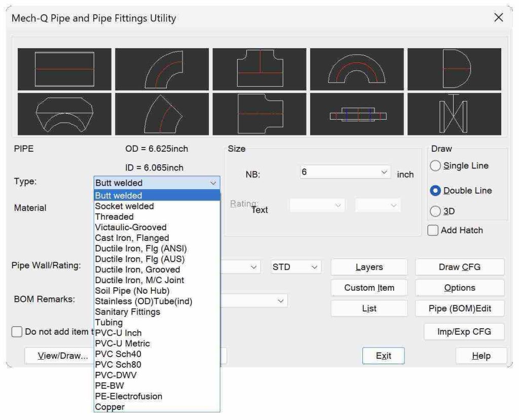
1. Identify the pipe type: From the Mech-Q dialog, for example, you can choose Butt Welded, Socket Welded or others listed in the selection.
2. Identify the pipe material: From the Mech-Q dialog, you can choose copper piping, PVC, or any other suitable materials in the materials selection.
3. Choose the pipe size: Based on your flow rate and pressure requirements, select the appropriate pipe NB or DN size if metric. In the inch system, the nominal bore is abbreviated as NB; in metric systems, it is “diameter nominal” or abbreviated as DN.
Steps to draw piping in CAD
Drawing a piping diagram requires some pre-planning and attention to detail. Here is a step-by-step process of a typical pipe drawing:
1. Determine pipe type, material, and size: Identify the type of pipe needed for your application, such as copper piping or PVC.
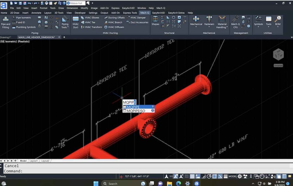
2. Create an isometric drawing: Start by sketching an isometric drawing of the pipe fitting. This will provide a 3D representation of the piping system and help visualize the layout. Label flow directions using arrows.
3. Take it one step further by creating a 2D or 3D drawing of your layout. Start by creating a simple wireframe sketch in either Ortho or 3D view. Please look at this tutorial to calculate the sheet size and final plot scale.
4. Choose 2D double-line or 3D piping draw options and proceed by snapping over the wireframe. With CAD, you can activate your Object Snaps so that Endpoints and Intersections to trace the schematic accurately.
5. Tagging options: Label the piping system’s components, valves, and fittings using tags or identifiers. You can use Mech-Q’s BOM to auto-label the drawing.
6. Dimension any critical areas and notate using multi-leaders as you draw piping in CAD. You can use the right text size and dimension scale based on your final plot scale.
7. Calculate pipe length: Mech-Q can tabulate the length of the pipes. With BOM activated, choose how you want to group the fittings and straight pipe.
8. Print your project: Select the required sheet size and title block. You can scale your drawing to fit within the borders and print it to paper or export it to a PDF file.
Following these steps, you can create a detailed and accurate piping diagram for your project. Use appropriate software, drawing templates, and scaling to ensure accuracy and efficiency.
Tips for creating an isometric pipe schematic
Creating an isometric drawing of the pipe system will help visualize the pipe route and what is required in your project. Isometric drawings are 2D but represent a 3D-like view and are usually not drawn to scale.
To accurately represent the pipe fitting in an isometric drawing, follow these steps:
1. Create a construction layer and sketch using ISO lines in your drawing area. A sketch helps determine the overall size of your drawing so that you can choose the appropriate scale factor before starting your project. It can also be used to locate various fittings quickly.
2. Using CAD, define the dimensions and angles required; in an ISO drawing, the pipe fitting dimensions can be noted NTS (Not to scale) as usually, an ISO is a sketch of the layout before it is drawn to full scale.
3. Take note of the length, width, and type of fittings and connections required. Additionally, you may need to identify any angles or bends in the pipe run.
4. Choose the appropriate symbols or straight pipes to input. You may want to copy fittings or sections of your project around in your drawing to save time.
5. As you go, check that the dimensions and angles are accurately represented in the drawing. Include any necessary details, labels
6. Make any necessary revisions to ensure the drawing is accurate—Re-check for any missing dimensions or notations that need to be included.
Add bill of materials and add other symbols as needed
Once you have a pipe layout, you can generate a bill of materials (BOM). The BOM lists all the materials required for the piping system, including pipe fittings, valves, and other components.
First, create a series of bubbles to notate the drawing. As you bubble, you can attach leaders that point to the various parts in your pipe run.
Since bubbling and table work side by side in Mech-Q, you can create a BOM automatically. You can insert the table into your drawing or export it to an Excel spreadsheet,
This way, you can create a cut list or estimate the quantities and costs of materials needed for the project.
Modify your existing pipe design
You will eventually need to modify and revise your existing pipe designs. Here are various ways you can edit your CAD pipe drawing:
1. Utilize CAD commands and tools: Take advantage of the various commands and features available within the software to make necessary modifications. For example, use essential tools like copy, erase, move, and stretch to adjust pipe segments, add or remove pipes, or rearrange the layout.
2. Avoid redrawing anything by hand. Always use pipe software like Mech-Q to do the heavy lifting. Remember, the whole advantage of CAD is never having to redraw anything by hand more than once.
3. Your drawing may outgrow the size of the paper. If this occurs, you may have to rescale your fittings, dimensions, and notes so that they are clear and concise when doing your final printing.
Print or export the completed drawing
Once you have completed your piping diagram, you may want to print or export it. If you need a hard copy or want to share the drawing electronically, several options are available.
If you print your drawing, please check that your printer settings are correct, ensuring the page size and layout are correctly configured. These print settings will also correspond with your paper space layouts.
You must adjust the print scale to fit the pipe diagram onto one page or split it into multiple sheets. It’s recommended that you understand how text and DIMSTYLE’s work in Paperspace in order to create prints that are easy to read.
Print Scale, Print Area, and Color are other print settings to check. The scale of your drawing is either to fit the paper size or typically set at 1:1 if you are printing from Paperspace.
The Print Area is typically your Layout or a Window selection if working in Model Space. The pen settings are where you can control the color of your print. Typically, these can be greyscale or monochrome. But colored drawings are an option as well.
You can choose a PDF driver in the Print Selection to email the print if required. By exporting the drawing, you can easily share it with others who may not have access to the original design software.
Choose the desired file format and save it to your desired location. By using printing or exporting options, you can ensure that your completed piping drawing is available in the best format for you.