Drawing AutoCAD pipe – methods and tips
In the video above please find some pipe drawing tips. We’ll be practicing directional distance and custom angles in order to draw our pipe in.
There are a few drafting tips within the video such as Directional Distance Entry and how to use SNAPANG to draw on an angle.
In this demo, I’ll show you how to create 2D piping in AutoCAD using the Mech-Q Piping module. The Mech-Q tools provide you with a very straightforward way to draw ducting, piping, mechanical, and structural schematics in AutoCAD. If you don’t have CAD, check out our AutoCAD alternative called AViCAD.
Initial drawing setup
First, we need to make sure that polar settings are set to 45-degree angles. You can find this setting in the status bar at the bottom of the screen in AutoCAD (or AViCAD). Also, make sure polar tracking is turned on.
Next, we’ll check the snap settings for the pipe in CAD (use the OS command shortcut). We can keep it simple and activate the endpoint, midpoint, and intersection.
Using Direction Distance Entry
Next, we’re going to start the line or L command to draw in the cad pipe route. We are essentially creating construction lines to define our pipe directions. We also want to use what’s called direct distance entry or DDE. First, we make sure we’re on the snap angle. Then point your cursor in the direction you need to draw. And then type in the distance using your keyboard.
Repeat this process, pressing Enter to repeat the Line command each time to draw your piping route. Each time make sure you are on the snap angle. Again. with polar tracking activated and then pointing your line in the direction you need, simply type in the distance.
Inputting our pipe schematic in CAD
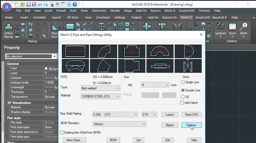
Once our construction lines are drawn we can load up Mech-Q (AutoCAD Piping module) and then choose the spec and size of our CAD pipe.
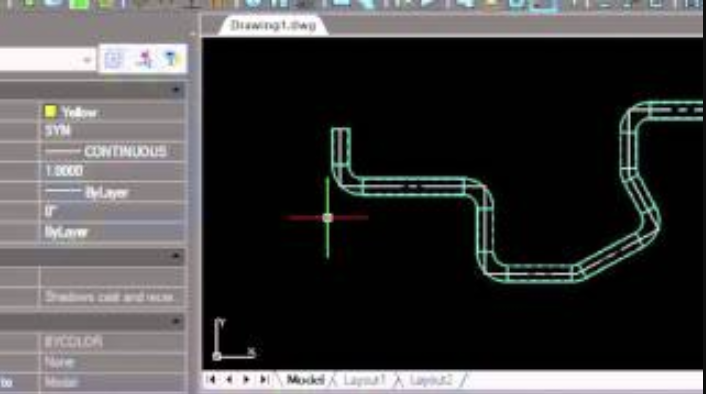
Choose a straight piece of pipe then choose draw. Now it is just a matter of snapping to the end point snaps and intersections of our construction line. As we. input the points, the elbows, and the straight pieces of pipe are drawn.
Drawing at an angle with SNAPANG
If we need a custom angle for our piping elbow, we can enter a custom angle/degree within Mech-Q. In this example, we use a 28.5 degree pipe.
We need to first rotate our cursor with the SNAPANG command. This way we can set the angle to 28.5 as required. Next, we input two points (at the centerline of the pipe) as prompted by AutoCAD. As you can see the cursor will change angle.
Now simply turn on ortho mode (F8 key) and enter another construction line at this angle. Again, we can use directional distance.
So now we can do the same as we did earlier and just snap over the endpoints of these construction lines.
Notice how the elbows auto-insert as you make 90-degree turns in our AutoCAD piping schematic.
Dimensioning our pipe drawing – DIMSTYLE & LTSCALE
So now that we have your pipe drawing drawn we can add some dimensions to it. Two commands you need to familiarize yourself with are D (or Dim Style) and UN (Units).
Other useful commands are DLI (to draw a linear dimension) and DAL (to draw an aligned dimension).
Next, if you look at the center line of the piping you may notice that it looks like one continuous line. In order to change that. We’ll go into LTSCALE. We can set this to a smaller value because of the zoom scale of our drawing in order for the center line spacing to show up.
Printing our pipe drawing
Now we’re ready to plot (PLOT command). We choose to print area. And window. Then we select the print area. At the upper left, look for a Print button. Print it out to a PDF or to your plotter/printer.
This is a super quick way to generate a plot layout. If you’re not too concerned about actually putting a scale on the drawing, once it’s printed.
For more visit https://www.cadavenue.com/get-started (AutoCAD is not required)