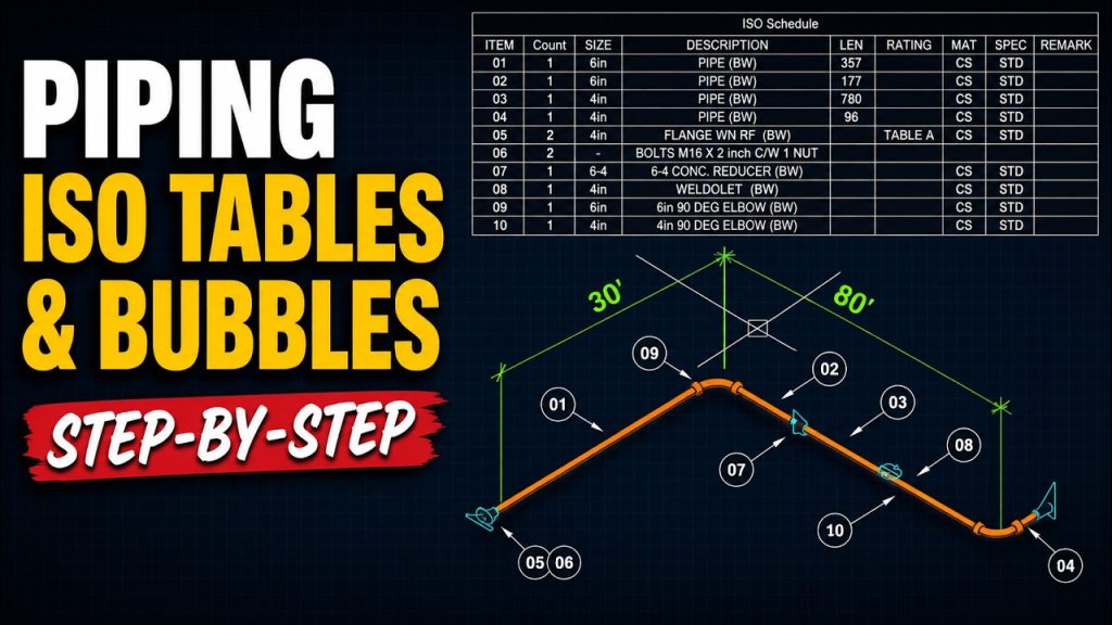
Learn how to link Excel to your DWG with Data Link and create a CAD table that updates when your spreadsheet changes, and how to write edits made in CAD back to Excel. This is lesson 3 of the free Piping Isometric Drawing course, continuing the piping isometric BOM from the previous video.
The 3 steps to an Excel Data Link table
- DATAEXTRACTION: reuse the template saved in the previous video to generate the BOM and export it to an Excel XLS file.
- DATALINK: create a link between the Excel spreadsheet and the DWG drawing.
- TABLE: insert the linked Excel data into the drawing as a CAD table.
Once linked, you can change the spreadsheet and update the table in your drawing without rebuilding it. This is useful for piping BOMs, schedules, material takeoffs and any drawing data you coordinate with Excel.
Step 1: Export the BOM with Data Extraction
Run DATAEXTRACTION New (DATAEXTRACTION in AutoCAD) and open the template saved in the last video. Because the template remembers your settings, you jump straight to step 6 of 8. Turn on the option to output to an external file and save it as ISO Project.
Step 2: Create the Data Link
Type DATALINK, create a new link called ISO Project and browse to the XLS file that was saved in your template folder. You’ll see a preview of the spreadsheet before you click OK.
Step 3: Insert the linked table
Type TABLE, choose From a data link and pick ISO Project. The table comes in small because it uses the default styles, so scale it up with QBOM SCALE to a 6″ text height to match the drawing.
Match the table format
The linked table brings in the Excel layout, so it won’t look like your original schedule at first. You only need to fix this once. I use a small LISP routine, MATCHTABLESIZE, that copies the size of a source table to another table; contact us if you’d like a copy. To center the text, select the cells and set the alignment to Middle Center.
Step 4: Put the schedule in paper space
The drawing is on an 8-1/2 x 11 sheet at 1/2″ = 1′-0″. Double-click into the viewport, set the viewport scale to 1/2″ = 1′-0″ (add it to your annotation scale list if it’s missing), then snap the viewport to the sheet corners.
To move the table into paper space, scale it with QBOM SCALE to a text height of 1/8″, then cut and paste it into the layout. In paper space, text is sized at its true printed height, typically 1/8″ to 3/16″, as if you measured it with a ruler on the printed sheet.
Step 5: Update the table from Excel
Open the XLS file in Excel or LibreOffice Calc, make your changes, and save it in the Excel 97-2003 (.xls) format. Back in CAD, run DATALINKUPDATE and choose Update data link to pull the changes into the table.
Step 6: Write changes from CAD back to Excel
Linked cells are locked. Select them and unlock them with Cell Locking, edit the text in CAD, and match the row heights (5/16″ here) so the table stays tidy. Then run DATALINKUPDATE with the Write data link option, and the change is written back to the spreadsheet.
Works in AViCAD and AutoCAD
This tutorial uses AViCAD, an AutoCAD alternative. The commands are the same in AutoCAD, except that AutoCAD uses DATAEXTRACTION instead of DATAEXTRACTION New.
Earlier lessons in this series
Next lesson: create a weld map
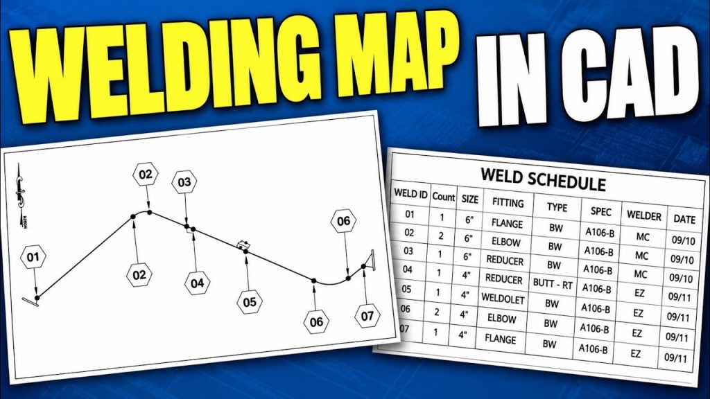
In Create a Welding Map in AutoCAD, we place weld markers on this isometric, bubble them and build a weld schedule. See all lessons on the course page.
Want to follow along? Download a free 30-day trial of AViCAD and Mech-Q.