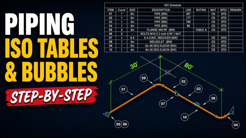
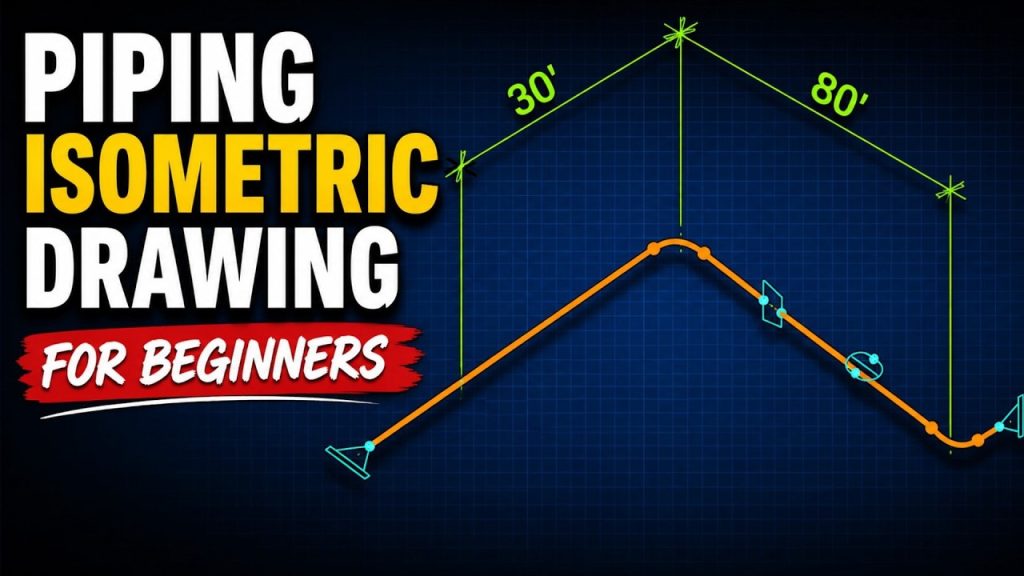
Learn how to create a welding map in CAD: place weld markers on your piping isometric, number and bubble each weld automatically, and build a weld schedule with Data Extraction. This is lesson 4 of the free Piping Isometric Drawing course, reusing the isometric from the earlier lessons.
The workflow is simple: QBOM Parts > QBOM bubbles > DATAEXTRACTION > weld schedule.
What you’ll learn
- Map table fields to weld data with QBOM Parts (Weld ID, Size, Type, Spec, Fitting, Welder, Date)
- Place weld markers and reuse previous values with the P (Previous) option
- Change the marker size and other settings
- Edit the information stored in an existing marker
- Number and bubble the welds with QBOM on their own layer
- Create the weld schedule with DATAEXTRACTION and update its headers
- Set up a separate weld map layout with per-viewport layers
Step 1: Prepare the isometric
Start with the finished isometric and use LAYOFF to hide the BOM bubbles layer. The weld map bubbles will go on a separate annotation layer so they don’t mix with your piping bill of materials.
Step 2: Map your weld fields with QBOM Parts
QBOM Parts lets you reuse the Mech-Q piping table design with your own field names. For the weld map, Item becomes Weld ID, Size stays Size, Spec stays Spec, Description becomes Type, Remark becomes Fitting, Rating becomes Welder and Quantity becomes Date.
Step 3: Place the weld markers
Choose New and pick each weld location. QBOM Parts then prompts for each field, for example 6″ size, butt welded type, A106B spec, the fitting (flange, elbow, reducer, weldolet), the date and the welder’s initials.
Reuse previous values
Every prompt remembers the last value, so you can press Enter to keep it. Type P (Previous) to pick from a history of values you’ve used before, such as butt welded with RT (X-ray) inspection, or earlier dates. New values are added to the history as you go.
Marker size and snapping
Change the marker size in the marker configuration (2 in this video, or 1.5 for smaller markers). If it’s hard to find the center of a weld node, use an object snap override.
Step 4: Number and bubble the welds with QBOM
Run QBOM, begin tagging a new area and, under Settings, set the layer to your annotation layer. You can switch the label type to a hexagon and change the starting number. Then pick each weld marker to place its bubble.
Fix a mistake after the fact
Weld markers store their data as block attributes. If you entered the wrong fitting, select the marker, edit the attribute in its block reference properties (elbow to flange, for example) and run QBOM again.
Step 5: Create the weld schedule with Data Extraction
Run DATAEXTRACTION New (DATAEXTRACTION in AutoCAD) and start from the template saved in the earlier BOM lesson. Show only attributes, and this time include only the QBOMPART entity instead of the pipe fittings. Sort by weld ID, arrange the columns, show or hide the count column, and insert the table.
Update the table headers
The table comes in with the standard Mech-Q piping headers. In QBOM Parts, choose Headers and click the table to replace them with your weld map field names.
Step 6: Set up the weld map layout
Copy the piping layout tab to create a second layout for the weld map. Because each viewport has its own layer settings, use LAYON to turn all layers back on, then use VPLAYER with Freeze and Current to freeze the weld map layer in the piping layout and the piping bubbles layer in the weld map layout.
Cut the table from model space (Ctrl+X), paste it into the weld map layout, and use SCALE with the Reference option to fit its width to the title block border.
QBOM Parts isn’t just for welds
QBOM Parts can itemize almost anything in a CAD drawing. Activate the QBOMPART entity in DATAEXTRACTION, and those custom items can be scheduled alongside your regular Mech-Q piping components in the same BOM or pipe schedule.
Earlier lessons in this series
See all lessons on the course page. Questions? Contact us or call 888-271-7121.
Software used in this tutorial
This tutorial uses AViCAD, a DWG-compatible AutoCAD alternative, with Mech-Q Piping. AViCAD is available with non-subscription, monthly and yearly licensing. Try it free for 30 days.