Learn how to create a piping isometric drawing from scratch in this beginner-friendly CAD tutorial. We start with a simple “napkin” isometric sketch on an 8-1/2 x 11 sheet, dimension it, then turn it into real piping with fittings using AViCAD and Mech-Q. It’s the first lesson in the free Piping Isometric Drawing course, and it’s easy to follow even if you’re new to CAD or to piping isos.
What you’ll learn
- Set DYNMODE and ISODRAFT so you can draw in isometric directions
- Sketch an isometric pipe route with ORTHO (F8) and F5
- Dimension an iso sketch and make the dimensions truly isometric with DIMEDIT
- Choose object snaps and set DIMSCALE for Mech-Q isometric fittings
- Draw pipe with MQ PIPE ISO and the Confirm Lengths option
- Add a reducer, a valve with weld neck flanges and fasteners, a flange and a weldolet
- Override lineweights and colors, and manage layers with LAYOFF, LAYISO and LAYON
Step 1: Set up the drawing for isometric input
Type DYNMODE and set it to 3 so command prompts appear at your cursor. Then type ISODRAFT and set the isoplane to Right, which rotates the cursor to the isometric angles. Turn on ORTHO with F8 to keep lines straight, and use F5 to switch between the left, top and right isoplanes as the pipe changes direction.
Step 2: Sketch the isometric pipe route
Using the LINE command on layer 0, sketch the pipe route. Think of it as a napkin sketch: the line lengths don’t need to be accurate, but the sketch does need to fit the paper, which here is an 8-1/2 x 11 sheet. Isometric drawings are not drawn to scale.
Step 3: Dimension the iso sketch
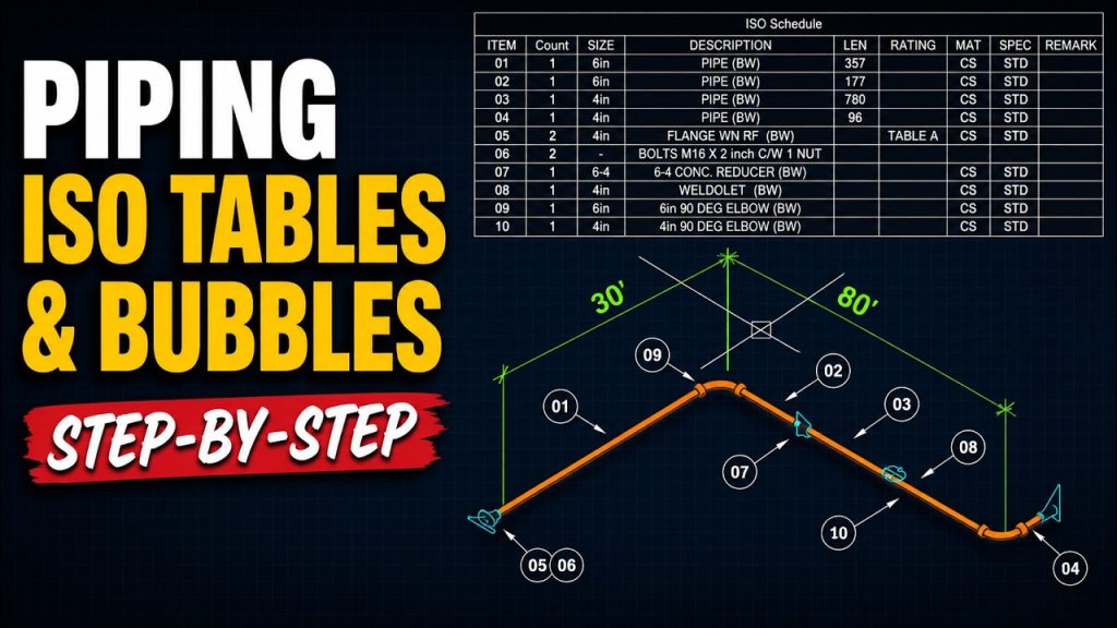
Add dimensions with DIMALIGNED, then double-click the dimension text, press Ctrl+A and type the real length (for example 30′ and 80′). To make the dimensions truly isometric, select them and use DIMEDIT with the Oblique option at 90 degrees. You can move them to a dimensions layer afterward.
Step 4: Object snaps and DIMSCALE
Keep your object snaps minimal. Endpoint and Midpoint cover most iso work; Node is useful in 3D. In the Mech-Q isometric module, DIMSCALE is simply a scale factor that sizes the fittings, weld nodes, dimensions and notes so everything fits on the sheet. In this drawing it goes from 64 down to 24. For a deeper look, watch AutoCAD DIMSCALE Explained.
Step 5: Draw the pipe with MQ PIPE ISO
Load MQ PIPE ISO (Mech-Q), set the pipe size to 6″ and the node size to 0.05, and pick the Right iso grid. Snap to the end of the construction line, use F5 to point the cursor in the flow direction, and use the NEArest snap to pick along the line.
Confirm Lengths
With Confirm Lengths turned on, Mech-Q asks for the real length of each pipe run (30′, 15′, 65′ and 8′ in this example). Because isometrics aren’t drawn to scale, these are the lengths that show up in your bill of materials. Turn the option off and Mech-Q uses the drawn length instead.
Step 6: Add the fittings
The Mech-Q mini dialog gives you 10 fittings to choose from.
Reducer
Pick the reducer, set the reducing size to 4″, then press Enter to start at the last point. Mech-Q keeps track of the new pipe size as you continue the run.
Valve with weld neck flanges and fasteners
Double-click the valve to open its sub-dialog, choose weld neck, place it and answer Yes to add fasteners.
Flange in plan view
Switch the iso grid to Top and place a flange, again adding fasteners.
Weldolet
Set the outlet size to 2″, snap to the midpoint of the pipe and point the branch in the direction you need.
Step 7: Lineweights, colors and layers
Optionally, select the pipe pieces and override the lineweight and color in the Properties palette. Use LAYOFF to hide layers such as the centerline layer, LAYISO to isolate the construction layer and erase the sketch lines, and LAYON to bring every layer back.
A great way to learn Mech-Q piping
The isometric module is the easiest place to start learning the Mech-Q piping tools. From there you can move on to 2D and then 3D piping, since all three are included. Mech-Q runs inside AViCAD, and it’s also available for AutoCAD and AutoCAD LT.
Next lesson: bubbles and the bill of materials
In Piping Isometric Drawing: Create BOM Tables & Numbered Callouts, we bubble this same isometric with QBOM and create the bill of materials (BOM) with Data Extraction. See all lessons on the course page.
More isometric piping tutorials
Software used in this tutorial
AViCAD is an AutoCAD-compatible CAD program, and Mech-Q Piping adds the piping and mechanical tools used here. Try them free for 30 days.