Before jumping into the drafting steps, it’s helpful to understand what isometric drawings are, why they’re used, and how isometric pipe drawings differ from standard orthographic views.
Introduction to Isometric Drawings
Isometric drawings are used in various industries, including engineering, piping, and construction. They usually represent complex systems, allowing professionals to visualize and communicate their designs effectively. These drawings are particularly valuable because they offer a three-dimensional perspective on a two-dimensional plane, making it easier to understand different components’ spatial relationships and dimensions. This section will delve into the world of isometric drawings, exploring their definition, importance, and applications.
What is Isometric Drawing?
An isometric drawing (ISO) is a method of visually representing three-dimensional objects in two dimensions. It involves drawing the object with the vertical lines remaining vertical, but the horizontal lines are drawn at 30 degrees to the baseline. This technique allows for a more accurate and detailed representation of complex systems, making it an essential tool for professionals in various fields. By using ISO drawing, designers can create a visual representation that maintains the proportions and relationships of the original object, providing a clear and comprehensive view that is easy to interpret.
Understanding Isometric Pipe Drawings
ISO pipe drawings are a type of isometric drawing designed explicitly for piping systems. They provide a detailed representation of the piping layout, including pipes, fittings, valves, and other components. These drawings are essential for ensuring proper alignment, accurate angles, and consistent scaling, making them a critical aspect of piping system design. Isometric pipe drawings help engineers and designers visualize the entire piping route, identify potential issues, and ensure all components fit together correctly. By using ISO pipe drawings, professionals can create more efficient and reliable piping systems, reducing the risk of errors and improving overall project outcomes.
Two Ways to Create Isometric Piping Drawings
Isometric piping drawings can be created manually using AutoCAD’s built-in isometric tools, or automatically using specialized piping software. Both methods are valid, and understanding each gives you flexibility depending on project size, complexity, and documentation requirements.
Method 1: Creating an ISO Pipe Drawing Using the F5 Shortcut (Standard AutoCAD)
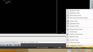
The simplest way to activate Isoplanes in vanilla AutoCAD is to use the F5 shortcut. Isoplane (also known as Isogrid) refers to the three isometric drawing planes (top, left, and right) used to create 2D isometric drawings that give the illusion of 3D depth.
This method allows you to toggle between different Isoplanes and draw at 30 or 60-degree angles, which is essential for ISO piping. You can also access drawing settings to adjust the Isoplane settings if needed.
For a detailed walkthrough of how to work in ISO mode, watch the video above:
Step-by-Step Process:
- Open AutoCAD: — Start a new drawing or open an existing one where you want to create an ISO pipe drawing.
- Activate ISO mode— Type command SNAPSTYLE. — Set this to 1 and Enter.
- Alternatively, check Drawing Settings: — If needed, you can further configure the Isoplane settings by accessing the Drawing Settings dialog: — Type DS in the command line and press Enter. — Navigate to the Snap and Grid tab in the Drawing Settings window. — Here, you can fine-tune the isometric snap settings by adjusting the grid and snap options for each Isoplane. — Apply the settings to match your project requirements, and click OK. Using the SW isometric view in AutoCAD is crucial for creating accurate isometric piping, as it helps manage the three-dimensional aspects of the design effectively.
- Toggle Isoplanes with F5: — Press the F5 key on your keyboard to toggle between Top, Left, and Right Isoplanes: – Top Isoplane: Aligns with the X-Y axis. – Left Isoplane: Aligns with the Y-Z axis. – Right Isoplane: Aligns with the X-Z axis.
- Draw at 30 Degrees: Select the Line command (L). Specify a starting point, then set the angle to 30 degrees relative to the selected isophane by typing 30 after specifying the start point and direction.
Example of how to draw a pipe valve in ISO view
Drawing in ISO provides a structured way to visualize and construct piping and mechanical components in a clear, dimensional format. This guide will cover key aspects of setting up your ISO drawing environment, using isometric views, and saving custom fittings for future use.
Start by selecting an ISO layout for consistent scaling, then use DIMSCALE in Mech-Q to ensure proportionally sized dimensions. Tools like ISOVIEW, ISOPLANE, and the F5 key help you navigate isometric planes, making it easier to construct accurate angles and connections. Finally, tool palettes offer a streamlined way to save and reuse symbols, such as a custom-drawn pressure release valve (PRV), across multiple projects.
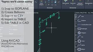
Check out this ISO video for a hands-on example of creating an isometric PRV valve and saving it to your tool palette.
Method 2: Create ISO Drawings With The Mech-Q Tools
Mech-Q (an AutoCAD add-on) and AViCAD (a standalone CAD application) provide a more efficient workflow for creating isometric piping drawings. These tools automate grid alignment, fitting placement, annotations, and BOM generation—making them well-suited for larger or more complex piping systems where speed and consistency matter.
Why Use Specialized Tools Like Mech-Q for Piping Isometrics
While it’s possible to create piping isometrics manually, specialized tools like Mech-Q are designed to eliminate many of the repetitive, error-prone steps involved in ISO drafting. The biggest advantages include:
- Automatic fitting placement
Elbows, tees, reducers, and branches are inserted automatically as pipe directions change, eliminating manual construction and alignment.
- Consistent scaling and proportions
Fittings, valves, welds, and annotations remain correctly sized using a single scale factor (such as DIMSCALE), ensuring uniform drawings across an entire project.
- Built-in Bill of Materials (BOM)
Pipes, fittings, and accessories are tracked as you draw, allowing you to generate accurate material lists without separate takeoffs.
- Faster revisions and updates
Changes to routing or pipe sizes automatically update connected fittings and BOM data, reducing rework when designs evolve.
- Standard CAD objects
Mech-Q creates native CAD entities, so drawings can be shared with contractors, fabricators, or clients who don’t have Mech-Q installed.
- Reduced drafting errors
By automating alignment, angles, and connections, the software minimizes common mistakes that occur in manual isometric drafting.
For engineers and designers producing multiple isometric drawings—or working on complex systems—these advantages translate into faster output, cleaner documentation, and fewer downstream issues.
Here is an overview of the steps we need to take when creating isometric pipe drawings:
Step 1: Setting Up the Isometric Drawing
When setting up the ISO drawing in AutoCAD, activate DIMSCALE in the configuration ribbon. Set the units as needed. The DIMSCALE factor should be set to 24 for working with half an inch. This number determines the size of annotations and dimensions in your ISO drawing.
Tip: To calculate your drawing limits, activate a viewport, zoom as required, or use the annotation scale list, draw a rectangle to reach the extent of the viewport, and finally close the viewport. Switch to model space to see your drawing area or limits.
- Launch Mech-Q or AViCAD: Open AutoCAD and load the Mech-Q add-on, or launch AViCAD directly if you are using it as standalone software.
- Start a New Drawing: Open a new drawing in Model Space and set the units to either English or Metric, depending on your project requirements. Define the drawing scale and sheet size. Create a title block as required.
- Configure DIMSCALE: — In the Mech-Q ISO Utility, set the DIMSCALE to match your desired scale. For example, if working in half-inch scale, set it to 24 to ensure proper scaling for annotations and dimensions. — Maintaining Consistent Scale: With the help of the setting, DIMSCALE, Mech-Q keeps the size of our firrings consistent throughout the drawing. This includes sizes of fittings, valves, and welds – to ensure they are proportional to each other.
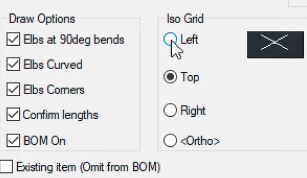
- Activate the Isometric Grid: — In the Mech-Q ISO dialog or AViCAD, choose the appropriate isometric grid that aligns with the 30-degree and 60-degree axes. — This grid allows us to draw and align the piping components in a 3D-like isometric perspective.
- Set Node Visibility and BOM Options: — Adjust the node settings (e.g., set the size to 0.03 for visibility). — Enable BOM options to itemize each pipe for easy tracking.
Step 2: Drawing the Piping Components
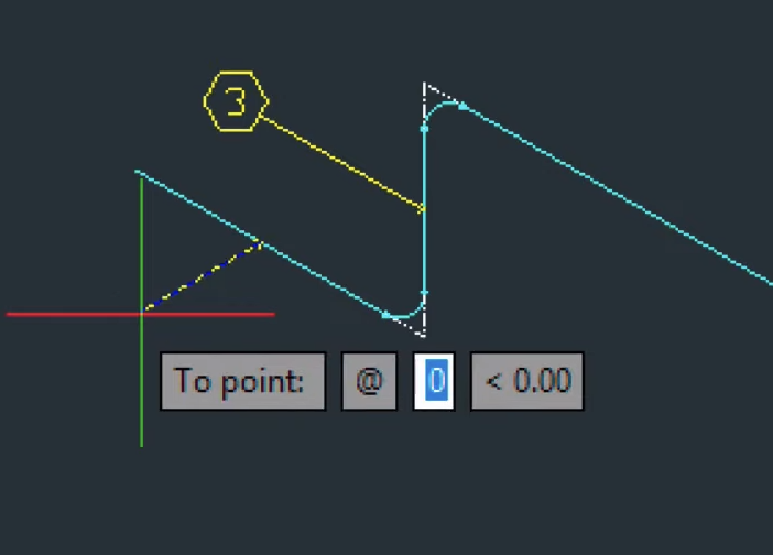
When working with Mech-Q for piping design, remember the step-by-step process for defining the pipe route, entering pipe lengths, and incorporating pipe fittings. This integration is crucial for ensuring that all elements align correctly and maintain an accurate isometric perspective in the design. This involves activating the left ISO grid, entering a series of points to define the pipe route, and then inputting the pipe lengths at specific points.
We’ll use direct distance input, which means specifying the precise distance between two points in a straight line. This provides an accurate way to define lengths or positions without relying on referencing points or measuring distances.
Let’s walk through the process together.
- Select Components: — Draw the Piping Components: Select the appropriate pipes, fittings, valves, and other components in the Mech-Q dialog box. — Choose common components like straight pipes, elbows, and tees to build your piping system.
- Draw the Piping Route: — Follow the isometric grid to plot the piping system by specifying points. — As you change directions, Mech-Q will automatically insert the necessary fittings, like elbows, based on the direction change.
- Input Pipe Lengths: — After drawing a pipe section, Mech-Q will prompt you to input the pipe length (e.g., 2 feet). — Continue specifying lengths as you add additional pipe sections. — Enable snapping as you enter points. This helps maintain the accuracy and proper alignment of the pipes and fittings.
- Switch Between Each Isoplane: You can change the grid view from Left ISO to Top ISO as needed, allowing you to draw pipes in different orientations without manually recalculating angles.
recalculating angles.
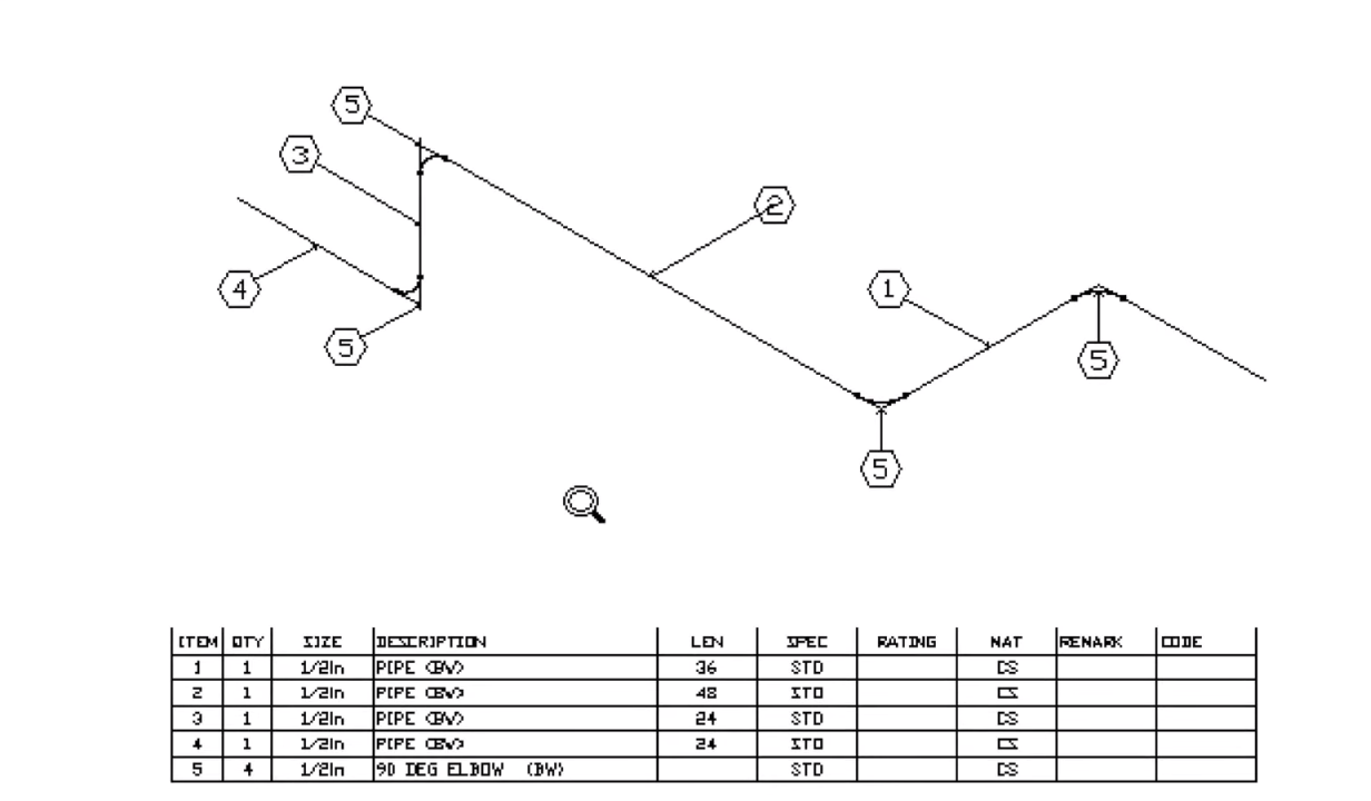
Step 3: Creating a Bill of Materials (BOM) and Annotations
In this step, we’ll add leaders and bubbles to our isometric piping using Ortho or Polar snapping. We’ll also discuss how to skip a bubble if needed and insert a BOM table or schedule of fittings. Additionally, we’ll explore scaling down the table using the SCALE command and moving it into the drawing sheet.
- Open BOM Settings: — In the ISO utility, navigate to the BOM settings and select your preferred table layout (e.g., a downward-building table).
- Itemize Each Pipe: — Enable the option to itemize each pipe for clear documentation of pipe lengths and materials.
- Generate the BOM: Mech-Q will automatically create the BOM based on the drawn components, listing all pipes and fittings and their respective lengths.
- Insert BOM Bubbles: — Label each pipe and fitting with leader arrows and place the BOM table within the drawing sheet.
- Scale the BOM Table: — If the BOM table is too large, use the SCALE command to resize it (e.g., 0.75 scale).
- Adding Annotations:
Mech-Q can also label information about the piping system, including pipe sizes, lengths, and ratings.

Step 4: Plotting / Printing Your ISO Drawing
Once the isometric pipe drawing and BOM are complete, you can plot or print the final output.
Review your drawing to ensure it is clear and easy to read. Sometimes, you may have to scale the BOM schedule to fit on your drawing sheet.
This step lets you clean and organize your drawing during your Plot Previews.
- Switch to Paperspace: — Load Paperspace to prepare the drawing for plotting.
- Set Plot Options: — Open the Plot dialog by typing PLOT. — Create a Plot Preview of your drawing. — Choose Monochrome in the pen settings to produce a clean black-and-white print.
- Choose Output Format: — Plot the drawing to paper or save it as a PDF for easy sharing.
About Paperspace and viewports
Paper space might sound complicated, but it’s not as daunting as it seems. It’s simply a way to organize and present different views and scales of a drawing within the same file. Once you get the hang of it, you’ll find it’s a useful tool for effectively managing and presenting your designs.
Within a Paperspace layout, we can define the scale, create various views (called viewports), and add annotations, dimensions, title blocks, and borders. We can select the proper paper size by switching between different layout tabs.
Our template has three drawing sizes available, and we will be working on a 24 by 36 sheet.
Once the sheet is loaded, type MS for model space to activate the model space viewport. Alternatively, you can also double-click on the viewport.
We need to set the zoom scale in the model space. You can set this to 1/24, which is our scale factor, and then type XP (1/24XP). You can also use the Annotative Scale list in the Status Bar, simply pulling down the scale list there.
How to scale your ISO drawing within a viewport
To understand AutoCAD scaling, you need to familiarize yourself with a few key concepts:
DIMSCALE: As discussed above, DIMSCALE is a system variable in CAD that determines the scale factor used for dimensioning. It controls the size of dimensions, and even text, fittings, and even weld points in Mech-Q.
Viewports: Viewports are windows into your paper space drawing that allow you to see different parts of your drawing at various scales. You can create multiple viewports to display different areas of your ISO piping drawing at different scales. Each viewport can also have its own scale.
Zooming: Zooming allows you to adjust the magnification level of your drawing viewport. You can use the ZOOM command to zoom into a viewport or use the Annotative Scaling drop-down in the Status Bar for accuracy.
Understanding these concepts will help you work with scaling in CAD and ensure that your isometric piping is accurately drawn at the desired scale.
Comparison: Traditional AutoCAD vs. Mech-Q/AViCAD
| Feature |
Traditional AutoCAD |
Mech-Q / AViCAD |
| Isoplane Activation |
DS, F5 and Status Bar |
Automatic ISO grid selection via dialog |
| Pipe and Fitting Insertion |
Manual |
Automatic insertion and pre-drawn fittings |
| Snapping and Alignment |
Object Snaps |
Automatic alignment along with Object Snaps |
| BOM Creation |
Manual |
Automatic BOM generation |
| Grid View Changes |
Manual |
Quick grid switching |
| Plotting/Printing |
Standard |
Titleblock and templates provided |
Creating isometric piping can be challenging, especially when comparing traditional hand-drawing methods with using AutoCAD software. Hand-drawing may be simpler, but Mech-Q offers more precision and complexity.
Best Practices for Isometric Drawings
Creating accurate isometric pipe drawings requires attention to detail and adherence to best practices. Here are some tips to help you improve your drawing skills:
- Use a Consistent Scale and Scaling Method: It is crucial to ensure that all elements of your drawing are to scale for accuracy and clarity. Consistent scaling helps maintain the proportions of different components, making the drawing more straightforward to read and interpret.
- Activate Polar Tracking: Polar tracking is a valuable tool for creating accurate angles and alignments in your isometric drawings. It ensures that lines are drawn at precise angles, which is essential for maintaining the integrity of the design.
- Use a Grid System: A grid system helps maintain consistent spacing and alignment throughout your drawing. You can create a more organized and professional-looking drawing by aligning your components to the grid.
- Include All Necessary Components: Your isometric piping should include all relevant components, such as pipes, fittings, valves, etc. This ensures that the drawing is comprehensive and provides a complete system representation.
- Use Clear and Concise Annotations: Annotations provide essential information about each component in your drawing. Use clear and concise annotations to label components, specify dimensions, and provide other relevant details.
- Regularly Review and Revise As Needed: Regularly reviewing and revising your drawings helps ensure accuracy and completeness. By checking your work and making necessary adjustments, you can create high-quality isometric drawings that effectively communicate your designs.
By following these suggestions above, you can create high-quality isometric drawings that effectively communicate your designs and ensure successful project outcomes. Whether you are working on a simple project or a complex piping system, these tips will help you produce accurate and professional drawings.
Conclusion
For simple projects, AutoCAD’s F5 isometric method provides a quick way to create ISO pipe drawings. For larger or more complex piping systems, Mech-Q or AViCAD offers automated tools that streamline fitting placement, annotations, and BOM generation. Both approaches are effective — the best choice depends on the scale and documentation needs of your project.
Additional Resources
- AutoCAD Isometric Forum: For additional support, visit the AutoCAD Forum.
- Mech-Q Tools: Learn more about Mech-Q.
- AViCAD Official Website: Explore AViCAD’s features at AViCAD.