Iso Piping – Creating a 2D ISO Pipe Valve Fitting: A Video Walkthrough for CAD Engineers
Sometimes you will need a fitting that is not available in a library. You must set up the drawing, snaps, and ISO views. Additionally, using ISO symbols and tool palettes can provide access to custom fittings for future use. This article will discuss the drawing setup, and how to draw a pressure release valve (PRV), scale it, and save it.
I. Setting up our ISO Piping Drawing
To start, we will choose a standard format, such as an eight-and-a-half by eleven format, This layout is widely accepted and makes it easier to share and print drawings to a PDF.
Another important step in the setup is checking and adjusting the DIMSCALE. This setting determines the size of the ISO pipe fittings and annotations in Mech-Q. By correctly setting the DIMSCALE, the drawings will accurately be resized according to the final plot scale. For more about scaling refer to the AutoCAD scale factor chart here.
In addition, using the ISOmetric utility in Mech-Q allows us to adjust the size of welding nodes. It ensures that the nodes are appropriately sized and aligned with the ISO standards.
To ensure the node setting is accurate, we need to test their display. By checking the display of nodes, we can make adjustments accordingly.
II. Drawing the Pressure Release Valve (PRV)
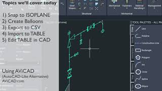
Before drawing the PRV, it is important to think about how we will save the ISO symbols for future use. Tool palettes are customizable collections of frequently used symbols, blocks, and commands. By saving ISO pipe symbols into tool palettes, users we can easily access and reuse them in different drawings, saving a lot of time and effort.
When drawing the PRV or any ISO symbol for that matter, it is recommended to draw it at a scale of one. This allows for scalability in different drawings and ensures that the symbol will be accurately represented regardless of the drawing’s size.
To facilitate the drawing process, users can toggle to the typing layer and set it as the current layer in the layers menu. This enables easy drawing and fitting by providing a dedicated layer for typing and annotation.
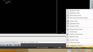
As we draw our ISO piping. or symbol manually, we need to set up our isometric views. There are a few shortcuts we can use such as the ISOVIEW, ISOPLANE command or pressing the F5 key. These shortcuts allow users to quickly switch between different isometric planes to speed up the drawing process.
III. Drawing the ISO Fitting
When drawing the fitting, it is helpful to reference an existing fitting, such as a check valve, in order to get a sense of size before starting the drawing. This helps to ensure that the proportions and dimensions of the fitting are as accurate as we can get them.
We can erase unwanted objects, copy or move entities then remeasure and recheck our results as needed.
To draw the ISO piping fitting, we can start by drawing lines based on the measured dimensions. Connecting the points and lines and then forming the outline of the fitting. This step requires some accuracy.
We can erase unwanted objects, copy or move entities as needed then remeasure and recheck our results. Lastly we connect the the weld nodes and check that the fitting as drawn can be properly positioned and aligned with the rest of the pipe system.
IV. Saving the Fitting
After completing the drawing, it is important to save the fitting for future use. By saving the fitting, users can easily access and reuse it in different projects. This saves time and effort, especially when working on similar pipe systems and related projects.
We need to create a block of the ISO pipe symbol first using the WB or Write Block command. The insert point will typically be at the center of fitting. We also need to define the block as inches or millimeters. We also need to convert it to a block then save it to a permanent folder on our drive that we know will always be available for the tool palette.
To save the fitting, we can simply drag it into the tool palette. Tool palettes act as a central data location for frequently used symbols, blocks, and commands. By dragging a block into a tool palette, users can easily access and insert it into future drawings.
How to use this ISO Pipe Fitting?
Now that we have a custom fitting we can proceed to the next sept of the ISO Piping Drawing input. Have a look.