Mastering ISO Piping with Mech-Q: A Step-by-Step Guide
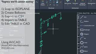
Welcome to today’s demonstration of how to draw ISO piping inside Mech-Q at CADAvenue! Mech-Q is a powerful suite of engineering tools designed to streamline your CAD projects. For those seeking more flexibility, we also offer a standalone version of Mech-Q called AViCAD. For additional details, visit our website. cadavenue.com/avicad.htm
This guide will cover the basics of drawing isometric piping using the Mech-Q toolbar and dialog interface. This step-by-step approach will help you easily create a professional-looking ISO drawing. Additionally, we’ll discuss traditional methods for those who don’t have access to Mech-Q.
Step 1: Selecting the ISO Module
First, select the ISO module from the Mech-Q toolbar. This module provides you with a series of shortcuts to creating detailed isometric drawings. Begin by setting up your drawing with three views: left, right, and top. (Or see the manual method below for those without Mech-Q).
Step 2: Drawing in the Left View
Draw the Initial Pipe:
Start with the left view. Draw a short piece of pipe using the drawing tools in the ISO metric module.
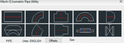
Add a T-Connection:
Use the dialog box to select a T-connection from the fittings library. Place it at the end of the pipe. Mech-Q’s dialog interface allows you to choose different fittings as you draw without having to search for them.
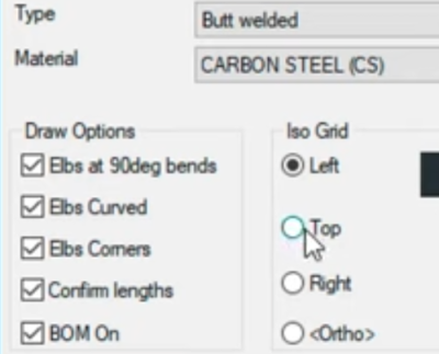
Adjust ISO Grid Views:
If you need to change your ISO grid views, simply select it from the dialog. As you input fittings, Mech-Q remembers the last point drawn, allowing you to return to it by hitting the enter key.

Showing Pipe Weld Locations:
Mech-Q will add pipe weld to each end of the pipeline. In the settings, Pipe Welds can be enlarged for additional clarity if needed in the dialog settings.
Manual Drawing Method Without a Plugin:
In AutoCAD, changing the ISO grid for different views such as left, right, and top involves using the ISOPLANE command. This command allows you to switch between the isometric planes, aligning the grid to the desired view. In the command type ISOPLANE followed by Left, Right, or Top (or use the F5 shortcut key to cycle through them) will set the grid to the corresponding view. For instance, ISOPLANE Left aligns the grid to the left isometric view.
Step 3: Drawing in the Right View
Continue from the T-Fitting:
Switch to the right view and continue drawing from the T-fitting.
Add Elbows and Flanges:
Return to the left view and add a couple more turns. Mech-Q will automatically place the elbows for you, simplifying the process. Select a flange from the dialog box and add it to your drawing. If you forget to add a flange, Mech-Q will remind you to ensure your drawing is complete.

Manual Fittings Method Without a Plugin:
Start by creating a comprehensive set of ISO fittings blocks following standard isometric conventions. Position the block accurately using AutoCAD’s snaps (OSNAP). Make sure each connection aligns with the isometric grid. It will speed things up to organize your library based on pipes, fittings, weld marks, annotations, and dimensions. Step 4: Finalizing the ISO Drawing
Add the Final Turn:
To finalize the ISO drawing, add another 90-degree turn. Each time Mech-Q will add an elbow in for you automatically.
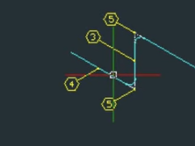
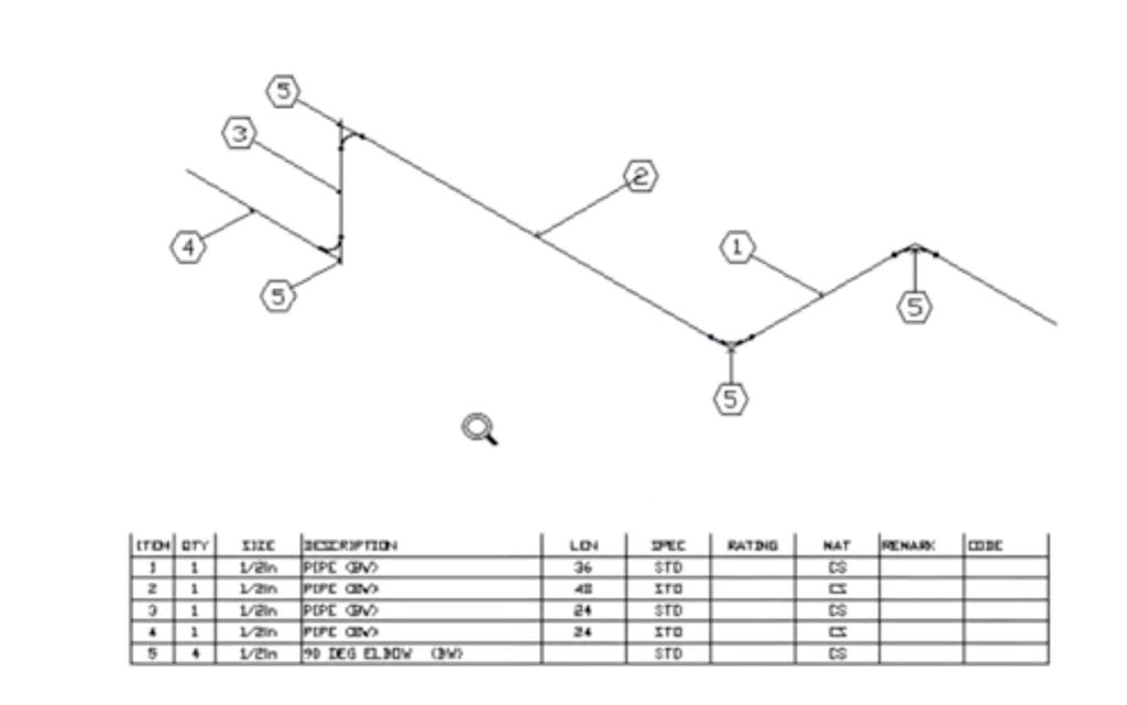
Create a Bill of Materials:
Once your drawing is complete, use Mech-Q to create a bill of materials (BOM). Apply labels to all parts, and the software will generate a schedule showing all listed parts. Arrange the schedule from bottom to top using the settings.
Manual BOM Method Without a Plugin:
One method is to create a bill of materials (BOM) in Excel first listing all components, quantities, and specifications. Once the BOM is complete, save it as a standard Excel file. To insert this BOM into AutoCAD, use the Paste Special command (PASTESPEC) or use the built-in Data Extraction Tool, which allows you to insert the BOM as an AutoCAD table.
Bubbling your parts can be done using the MARKER command, Then place the bubble at the desired location on the component. You’ll need to order the bubbles in a sequence that corresponds to the labels in your BOM.
Adding Dimensions to Your Drawing
Isometric Dimensions:
After completing the bill of materials and schedule, create isometric dimensions, such as the whole dimension and the height dimension for the short run. These dimensions are small but effectively illustrate the process.
Override Dimensions:
If needed, you can override dimensions. After entering the second point, input any number you desire, such as 10 feet or 3.5 inches. This flexibility allows you to customize your drawing to meet specific requirements.
Adding Text and Final Adjustments
Add Text Annotations:
Add text wherever necessary by entering two points and typing the desired text. This is particularly useful for adding notes and annotations to your drawing.

ISO scaling:
To change the scale of text, dimensions and even fittings, Mech-Q uses the DIMSCALE setting. The default is 1, but try 12, 24 or 48 for other typical scale factors, Mech-Q does most of the heavy work like ISO angles, fitting orientation and scaling.
Manual Method Without a Plugin:
Follow the method above to set the ISOPLANE. The text rotation angle needs to match the isometric orientation—typically 30 degrees for left and right isoplanes and 0 degrees for the top isoplane.
You’ll need to manually adjust the dimension lines and text to align with the isometric angles. For isometric dimensions, the Oblique property of the dimension can be modified to match the angle of the isometric view, typically 30 or -30 degrees. This can be done by selecting the dimension, right-clicking, choosing Properties, and setting the Oblique angle.
Conclusion
We hope you’ve enjoyed this demo of ISO piping in Mech-Q. The tools and features highlighted here are designed to make your CAD projects more efficient and accurate. For more demonstrations and detailed guides, visit our website at kentavenue.com. If you have any questions or need further assistance, feel free to call us at (888) 827-7228.
Mastering ISO piping with Mech-Q opens up a world of possibilities for your CAD projects. With this intuitive interface, you’ll be able to create professional-grade drawings with ease. Don’t forget to check out our other demos and resources to further enhance your drawings.