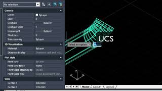
The Weld Mapping Software used in the video above was demoed inside AViCAD (a 2D/ 3D AutoCAD-Like alternative)
What is a Weld Map?
A weld map visually represents the welds performed on a piping system. It provides a clear and concise overview of the welding operation, including each weld’s location, type, and size. Weld maps are commonly used in industries such as oil and gas and manufacturing, where weld quality is critical.
Importance of Isometric Drawings
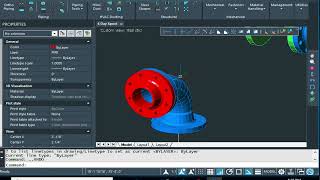
Weld mapping is a process that involves documenting and recording weld joints for quality assurance, traceability, and compliance purposes. Creating an Isometric drawing is an essential step when doing weld maps. By creating isometric drawings, welders can create a visual map of the welds to identify, inspect, and record each joint.
One important aspect of documentation is weld map labeling and creating a schedule. This process helps identify and track welds, ensuring they meet specifications and standards. The video below will guide you through the steps of weld map labeling and creating a schedule.
Weld Map Labels and Schedules
Accurate weld map labeling is essential for several reasons. Not only does it provide a way to inspect, identify and trace each weld, but it also provides a method to locate potential issues or defects in the welds so that they can be repaired in a timely fashion. A weld map can also ensure correct procedures and materials are used.
Steps To Create a Weld Map Schedule:
1. Identify Welding Points: After reviewing the project, identify all the points where welding inspection is required. Mark these points on the drawings or create a list for easy reference.
2. Assign Unique Identifiers: Assign unique identifiers to each welding point. This can be done using numbers, letters, or a combination. Make sure that the identifiers are clear and consistent throughout the project. In the video we use Mech-Q, our CAD engineering software to create our identifiers.
Weld Map Identifiers
4. Record Welding Details: For each welding point, record relevant details such as the welding process, electrode type, filler material, and other procedures. This information will help ensure the correct welding specs are followed.
5. Create a Weld Map: Create a visual representation of the welds using the design drawings and the recorded information. This is where software add-ons like Mech-Q can save you time. Include the unique identifiers and any additional information relevant to each weld.
6. Label the Weld Map: Once the weld map is created, label each weld with its unique identifier. This can be done directly on the map or by creating a separate legend corresponding to the identifiers.
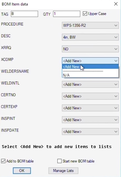
7, Create a BOM Schedule: Once labels are located you can create a Weld Map table or schedule. In the video above we are using the General BOM Utility found in the Mech-Q General Tools. You will notice that we have both a Piping BOM and General BOM present in the same drawing.
Alternatively if you did not want to create a BOM you could also create a Weld Map table in Excel then import it into your drawing and label it using multi-leaders as demonstrated in the Excel video.
In this video above we show you:
• How to set text heights for balloons and tables
• How to calculate DIMSCALE so that our annotations are clear and easy to read.
• How to customize a table (in our example, we show you how to create a weld map)
• How to load the custom pulldowns
• How to use paper space to insert the schedules and then plot
7. Review and Update: Regularly review the weld map and update it as new welds are performed, or changes are made to the welding process. This will ensure that the documentation remains accurate and up to date.
By following these steps, you can create a weld map and a schedule that will document and allow you to manage your welding operations more efficiently. Creating accurate and organized drawings is essential for ensuring the quality and safety of welds.
Below is a link to table of contents so you revisit different sections of the video later using the bookmark links provided. This video is about 25 minutes so you may want to absorb it at your own pace.
Use this Weld Map PDF download to go with the video. It not only contains bookmarks but screenshots of the Weld Map Drawing process to help you create a Weld Map Table.